Engineering analysis / 2026
Prosthetic Limb
Analysis.
Shaping a blade.
Understanding its response.
I used finite element analysis to explore how geometry and material change a running blade’s stress, flexibility and vibration behaviour.
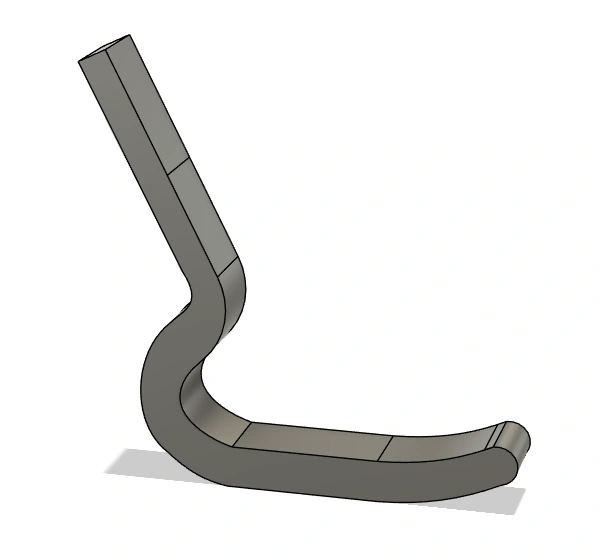
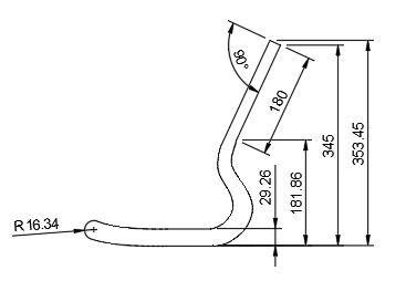 Geometry from the report
01 / Defining the model
A spring-like structure.
Several competing demands.
A running blade needs flexibility for elastic energy storage, alongside structural durability and a suitable dynamic response. This study compares those structural responses under a consistent, simplified ANSYS setup.
The analysis setup
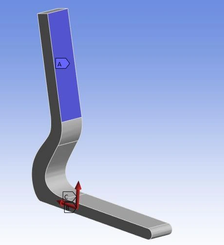
- 01Constrain the upper connection
The mounting area is modelled as a fixed support. Displacement increases towards the free foot end.
- 02Apply normal and friction loads
Motion is defined along +x, with friction acting in −x. The report uses simplified static loading.
- 03Compare like with like
Two materials, two geometries and three quadratic mesh sizes support the comparison.
CFRP, represented as an equivalent isotropic material.
The model uses E = 65 GPa, ν = 0.30 and ρ = 1,550 kg/m³. It simplifies the overall response without defining a laminate lay-up; fibre direction and stacking effects remain outside this analysis.
02 / A change in the load path
From a straight foot
to a smoother return.
The initial blade paired a curved body with a straight contact section. I introduced a raised front tip and a smoother lower profile to investigate whether the geometry could increase stiffness and improve its modal response.
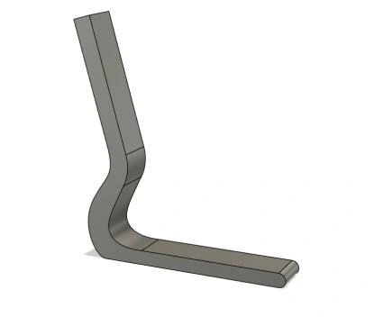
A straight contact section.
Approximately 296 mm overall horizontal length, with a 250 mm foot section.
View dimensioned drawing ↗A raised tip and smoother curve.
353.5 mm overall height, a 90 mm main transition radius and a 16.3 mm tip radius.
View dimensioned drawing ↗Reduce the severity of the curved transition while changing the balance between stiffness and mass.
03 / Read the response
Same analysis.
Different structural behaviour.
Switch material and result to compare the baseline and iterated fine-mesh solutions. These are the original ANSYS outputs from the report, with rounded values brought forward for comparison.
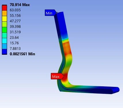
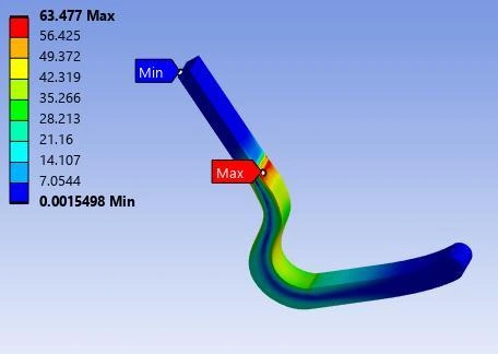
Each ANSYS plot uses its own legend range. Compare the numerical values, not colour alone. The report rounds final CFRP stress to 63.4 MPa; the source contour displays 63.477 MPa.
| Measure | Baseline | Iterated |
|---|---|---|
| First natural frequency | 97.2 Hz | 147 Hz |
| Maximum deformation | 6.68 mm | 3.24 mm |
| Peak equivalent stress | 70.9 MPa | 63.4 MPa |
| Approximate mass | 0.8 kg | 1.3 kg |
Higher frequency at lower reported mass than aluminium. Fibre direction and laminate stacking are not represented in this simplified isotropic model.
first natural frequency
maximum deformation
Stiffer also meant heavier.
The report gives approximately 0.8 → 1.3 kg for CFRP. Lower deformation and a higher first mode improve these analysis metrics; they do not alone establish better energy return or running performance.
04 / Check the numerical foundation
Refine the mesh.
Watch the result settle.
Quadratic elements were refined globally and around the inner curve and foot contact region, where stronger stress gradients and bending were expected. The reported modal results changed little with finer meshes.
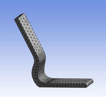
Global / local element size
First natural frequency / Hz
Replotted from the report’s modal results. Both geometries exceed the brief’s 50 Hz threshold for both materials.
View the numerical convergence table
| Model / Hz | Coarse | Medium | Fine |
|---|---|---|---|
| CFRP / Iterated | 149 | 148.1 | 147 |
| Aluminium / Iterated | 117.6 | 116 | 115 |
| CFRP / Baseline | 97.7 | 97.6 | 97.2 |
| Aluminium / Baseline | 76.7 | 76.5 | 76.3 |
Mesh stability supports the numerical comparison. It does not remove uncertainty in the boundary conditions, loading or material model.
05 / Durability, with different evidence
Two materials.
Two assessment methods.
The aluminium model could be assessed with the ANSYS fatigue tool. Without a reliable S–N curve for the chosen CFRP approximation, I used a separate strength-based screening.
The reported minimum life exceeds the 10⁶-cycle criterion in both geometries under the modelled conditions.
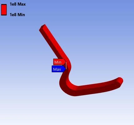
A model prediction under the stated setup, rather than measured service life or physical endurance validation.
A representative 800 MPa strength divided by a safety factor of 3 gives the report’s allowable-stress threshold.
A margin, not a fatigue-life prediction.
The static stress is well below this simplified threshold. The check does not model laminate fatigue, damage accumulation or a number of cycles to failure.
No CFRP S–N fatigue analysis was performed in this study. Report pp. 6 and 11.
Reflection / From numerical improvement to physical performance
The next model
needs more of the real world.
The geometry change improved the reported stress, displacement and modal results. My main takeaway is to separate that numerical improvement from claims about how the blade would perform for an athlete.