SUSTAINABLE PLANE SEAT
A lighter seat.
A longer life.
An economy-class seat designed around what we keep, what we replace, and what happens next.
Explore the seat system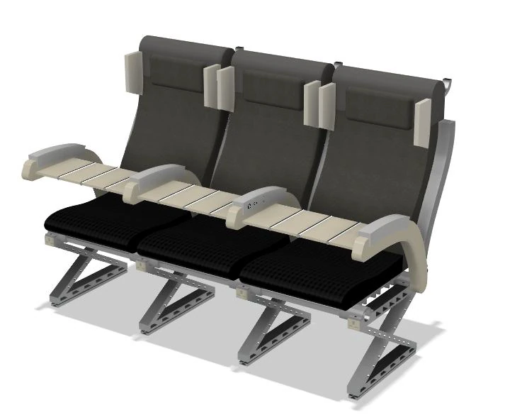
A design concept,
evaluated through CAD
and material modelling.
01 / THE BRIEF
Less to carry.
More to consider.
Weight is only one part of the brief. A lighter seat still needs to feel comfortable, stay affordable and survive years of service.
Comfort matters.
So does the fare.
The report’s persona, Emma, is an international student who makes two long journeys a year. Soreness, sleep and the cost of economy travel frame the needs.
Comfort
Soreness and sleep supportDual-density cushioning, breathable zones and adjustable neck support.
Affordability
Keep economy accessiblePreserve useful comfort within a compact short-haul seat architecture.
Maintenance
Avoid whole-seat replacementSeparate the durable structure from wear parts and electronics.
Recovery
Make materials separableAccessible joints, material labels and distinct recovery routes.
DESIGN TARGETS
Requirements guide the concept.
They are not validated performance.
- Seat pitch
- 74–76 cm
- Cushion thickness
- ≥50 mm
- Seat mass
- ≤10 kg
- Recyclable mass
- ≥70%
02 / PRODUCT ARCHITECTURE
One seat.
Three service lives.
A long-life frame, replaceable comfort layers and independent accessories turn a single product into a serviceable system.
03 / THE PASSENGER INTERFACE
Details at
human scale.
Comfort comes from a sequence of small decisions: where the head rests, how the tray opens and how the controls feel.
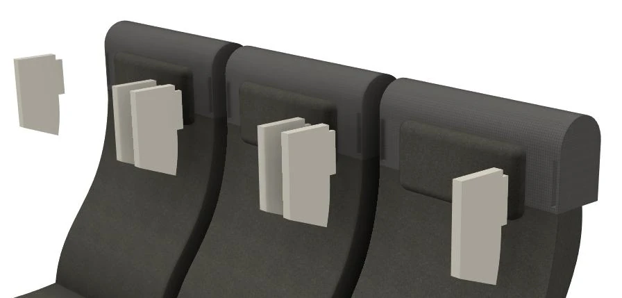
Support that adjusts.
Height-adjustable neck rests and detachable side supports address sleeping posture and a sense of personal space.
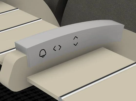
A physical reference.
Raised controls locate recline and attendant call at the armrest.
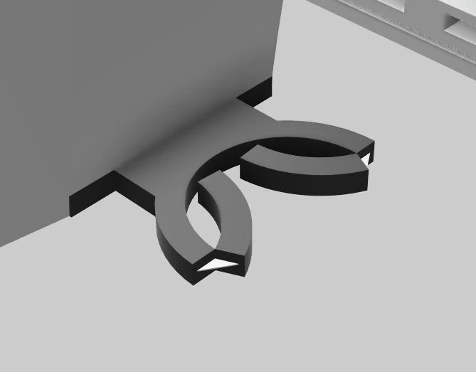
Useful. Replaceable.
A folding cup holder is a small module with its own service path.
04 / DESIGN FOR DISASSEMBLY
Design the way
back out.
Disassembly follows four stages, from the most frequently replaced parts to the longest-lived structure. Each connection has a release method and a proposed material route.
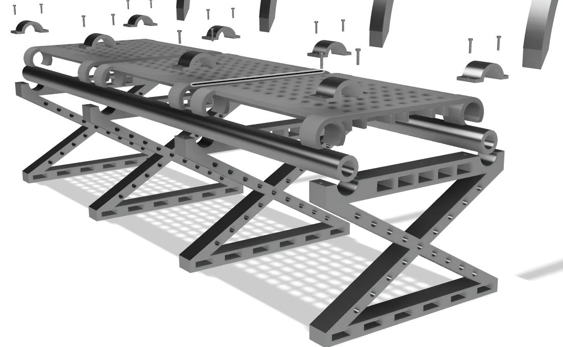
Reuse next.
Recover last.
- 01
Release the soft goods
Covers · headrests · cushion cores
Remove the parts that need frequent cleaning or replacement before disturbing the seat structure.
Connections & material route
- Release method
- Zips, hook-and-loop and snap fits
- Proposed route
- Separate textiles and foam
- 02
Disconnect the accessories
Tray · cup holder · power · controls
Unplug the electrical modules and remove individual accessories from their common mounting points.
Connections & material route
- Release method
- Small Torx / hex tools + keyed connectors
- Proposed route
- Separate electronics and fittings
- 03
Lift out the pans and shells
Perforated pans · trims · armrest beams
Release the polymer components without bonding them permanently to the metal frame.
Connections & material route
- Release method
- Clips and accessible mechanical fasteners
- Proposed route
- Sort GF thermoplastic parts
- 04
Recover the primary structure
Shared base · back supports · track fittings
Inspect the frame for reuse first. At its final end of life, separate the metal families for recovery.
Connections & material route
- Release method
- M5 / M6 bolts and seat-track fittings
- Proposed route
- Separate aluminium and steel
Proposed recovery routes depend on material identification, collection and suitable recycling facilities. The sequence is a design proposal, not a timed physical teardown.
05 / MEASURING THE CONCEPT
Lighter, with
limits in view.
Final concept estimates from the material model and Granta EduPack eco-audit. Reductions use the report’s baseline assumptions; the energy and carbon figures exclude operational flight energy.
Seat mass
kg / passenger place
Embodied energy
MJ / passenger place
Carbon footprint
kg CO₂ / passenger place
The final concept is
0.6 kg above target.
The early estimate and final model are different design stages. Further frame optimisation remains an open task.
A modelled indicator, not a recycling percentage. The source worksheet assumes 50% recycled input and 90% collection for aluminium; plastics use 30% and 60% respectively.
Read the assessment boundary & source data
This eco-audit excludes operational flight energy. The report assigns zero to the use phase. The 1,973 MJ and 129 kg CO₂ values divide the first-life totals for a three-seat row by three. They should not be presented as a complete aircraft-use life-cycle footprint.
| Phase | Energy (MJ) | CO₂ (kg) |
|---|---|---|
| Materials | 5,260 | 338 |
| Manufacturing | 532 | 39.9 |
| Transport | 119 | 8.54 |
| Use (excluded) | 0 | 0 |
| Disposal | 14.2 | 0.995 |
| First-life total¹ | 5,920 | 387 |
¹ Totals as rounded in the report. End-of-life potential is listed separately there (−3,910 MJ; −256 kg CO₂) and is not subtracted from the headline values above. Safety, comfort and in-service durability remain to be physically validated.
06 / BEYOND THE OBJECT
A seat needs
a return route.
Circularity depends on the people who make, operate and maintain the seat. The stakeholder map connects physical parts with the information needed to keep them useful.
- 01 / SEAT OEM & SUPPLIERS
Make & document
Choose traceable materials. Label components and create the bill of materials.
- 02 / AIRLINES & PASSENGERS
Use & learn
Record service history and gather comfort feedback during operation.
- 03 / MAINTENANCE & OEM
Inspect & renew
Replace worn modules. Grade returned frames for repair and reuse.
- 04 / MATERIAL RECOVERY
Separate & return
Use the material record to route parts into suitable recovery streams.
Close the information loop. Inspection records and passenger feedback return to the design team; the bill of materials and service manual travel with the seat.